Advanced Computer Architectures

A note for the course of Advanced Computer Architectures.
L00 Intro
L01 Pipelining: Basic Concepts
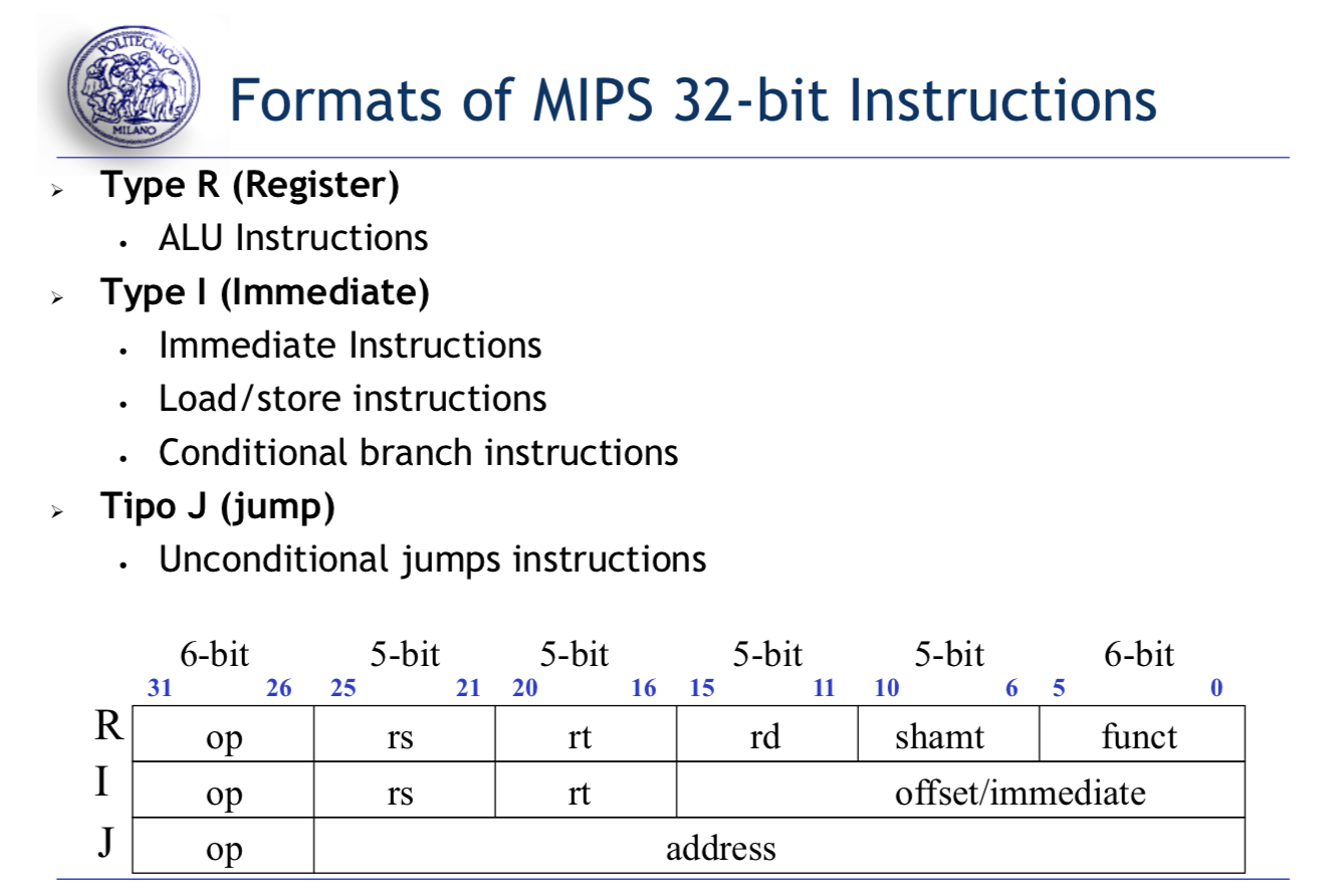
MIPS
- ALU Instructions: add $s1, $s2, $s3
- Load/Store Instructions: lw/sw $s1 offset($s2)
- Branch Instructions: beq/bne $s1, $s2, L1
R-Format for Instructions
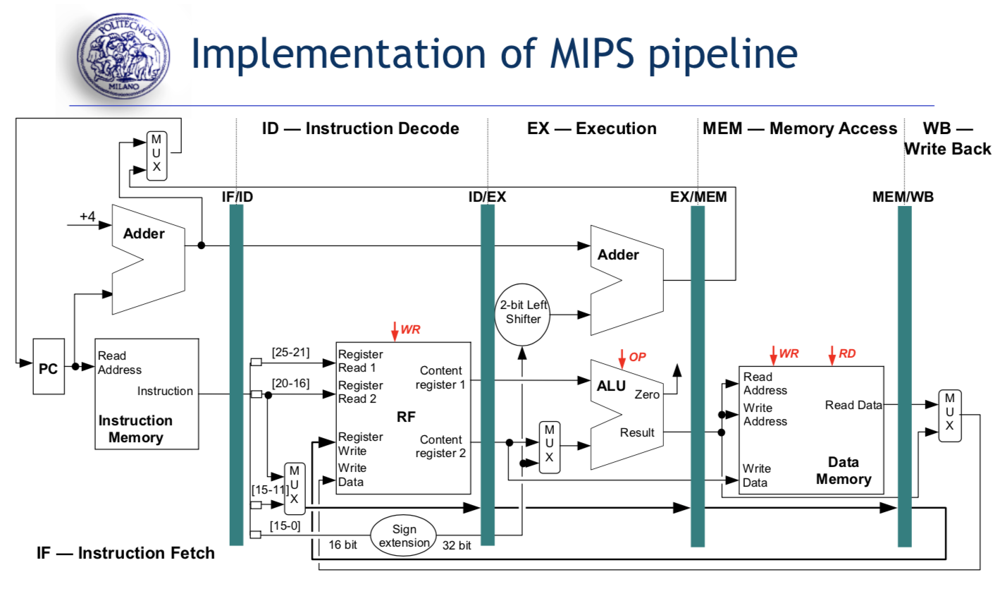
Phase of execution of MIPS Instructions:
- Instruction Fetch
- Instruction Decode and Register Read
- Execution
- Memory Access
- Write Back Cycle
Different type of Instructions(R/I/J) may require different execution phase. In an ALU R-Instruction, there is no needs for the memory access.
Pipelining
Basic idea: The execution of an instruction is divided into different phases (pipelines stages), requiring a fraction of the time necessary to complete the instruction.
The pipeline stages must besynchronized: the duration of a clock cycle is defined by the time requested by the slower stage of the pipeline.The goal is to balance the length of each pipeline stage.
一个MIPS Instruction可能需要8ns,但是为了在宏观上实现pipelining,我们把5个阶段分开,并且将最长事件的阶段作为一个clock cycle,虽然每一个Instruction花费的时间变多了,但是由于pipelining,整体的output提高了。
Pipeline Hazards
- Structural Hazards: Use the same resource from different instructions simultaneously
- Data Hazards: Attempt to use a result before it is ready
- Control Hazards: Attempt to make a decision on the next instruction to execute before the condition is evaluated.
No s-hazards in MIPS
While d-hazard in very possible (RAW)
WAW/WAR occur more easily when instructions are executed out-of-order.
Data Hazards Solution:
- Insertion of nop
- Rescheduling to avoid correlating instruction too close
- Insertion of stalls
- data forward or bypassing (uses temporary results stored in the pipeline registers instead of waiting for the write back of results in the RF)
The differnce between nop and stalls is that nop is an instruction, while stalls is only stalled for one clk
Forwarding Paths
EX/EX path
MEM/EX path
MEM/ID path
MEM/MEM path (for load/stores)To avoid the read/write RF in one clk, we assume the RF read occurs in the second half of clock cycle and the RF write in the first half of clock cycle.
Performance Metrics in Pipelining
IC = Instruction Cound
Clk Cycles = IC + #Stalls + 4
CPI = Clk Cycles/IC
MIPS = fclock/(CPI*106)
The ideal CPI on a pipelined processor would be 1, but stalls cause the pipeline performance to degrade form the ideal performance.
L02 Branch Prediction Techiniques
Control hazards: Attempt to make a decision on the next instruction to fetch before the branch condition is evaluated.
Branch Hazards Solution
Conservative Assumption: stall the pipeline until the branch decision is taken, and then fetch the correct instruction.
Conservative Assumption with Forwarding
Early Evaluation of the PC: get the result of the branch prediction in the end of ID state.
Branch Prediction Techniques
Static Branch Prediction Techniques
The actions for a branch are fixed for each branch during the entire execution. The actions are fixed at compile time.
- Branch Always Not Taken: if the branch is actually taken, make the fetched instruction a nop.
- Branch Always Taken
- Backward Taken Forward Not Taken: backward-going branches are predicted as taken, while forward-going branches are predicted as not taken.
- Profile-Driven Prediction
- Delayed Branch: The MIPS compiler always schedules a branch independent instruction after the branch. (there are 4 ways in Delayed Branch: From Before/From Target/From fall-throuogh/From After)
Dynamic Branch Prediction Techniques
The decision causing the branch prediction can dynamically change during the program execution.
Schemes:
Branch Outcome Predictor
Branch Target Predictor/Branch Target Buffer
- Branch History Table
- Correlating Branch Predictor: Branch predictors that use the behavior of other branches to make a prediction are called Correlating Predictors or 2-level Predictors.
- Two-level Adaptive Branch Predictor: The first level history is recorded in one (or more) k-bit shift register called Branch History Register (BHR), which records the outcomes of the k most recent branches. The second level history is recorded in one (or more) tables called Pattern History Table (PHT) of two-bit saturating counters.
- Branch Target Buffer
L03 Instruction Level Parallelism Part I - Introduction
Dependencies
- Data Dependencies(True Data Dependences): RAW-data dependence/WAR-anti dependence/WAW-output dependence
- Name Dependencies: 2 instructions use the same register or memory location, but there are no flow of data between the instruction associated with that name.
- Control Dependencies
Multi-cycles: Basic Assumptions
- We consider single-issue processors.
- Instructions are then issued in-order.
- Execution stage might require multiple cycles, depending on the operation type.
- Memory stage might require multiple cycles access time due to data cache misses.
ILP = Exploit potential overlap of execution among unrelated instructions
While overlapping possible only if: NO structural/RAW/WAR/WAW/Control hazards
In a multiple-issue pipelined processor, the ideal CPI would be CPI ideal < 1. (Dual issue means there are two lanes to execute the two pipeline simutanously)
The issue width is the number of instructions that can be issued in a single cycle by a multiple issue processor
Two Strategies to support ILP: Dynamic Scheduling/Static Scheduling
Hazards due to data dependences that cannot be solved by forwarding cause stalls of the pipeline: no new instructions are fetched nor issued even if they are not data dependent.
Solution: Allow data independent instructions behind a stall to proceed. (Enables out-of-order execution and completion/commit)
Dynamic Scheduling: Superscalar Processor [Expensive]
Dynamic Scheduling: The hardware reorder dynamically the instruction execution to reduce pipeline stalls while maintaining data flow and exception behavior.
- Basically: Instructions are fetched and issued in program order (in-order-issue)
- Execution begins as soon as operands are available – possibly, out of order execution – note: possible even with pipelined scalar architectures.
- Out-of order execution introduces possibility of WAR and WAW data hazards.
- Out-of order execution implies out of order completion unless there is a re-order buffer to get in- order completion
Static Scheduling: VLIW
VLIW (Very Long Instruction Word) processors expect dependency-free code generated by the compiler
L04 Instruction Level Parallelism Part II - Scoreboard
Basic Assumptions
Single Issue processors
IF might fetch either into an IR or into a queue of pending instructions
Instructions are then issued from the IR or from the queue
EX stage may require multiple cycles
MEM stage may require multiple cycles
Scoreboard Pipeline: in-order issue but out-of-order execution/completion
Due to out-of-order completion WAR and WAW hazards can occur.
Scoreboard has 4 stages
- Issue (decode and check no WAW) [INORDER]
- Read Operands (wait until no RAW) } [OUT OF ORDER]
- Execution [OUT OF ORDER]
- Write result (check no WAR) [OUT OF ORDER]
Optimisations:
check for WAW postponed in WRITE Stage instead of in ISSUE Stage
forwarding
L05 Instruction Level Parallelism Part III - Tomasulo
Scheme
- ISSUE: [IN ORDER] check for structural hazards in RESERVATION STATIONS (not in FU)
- EXECUTION: [OUT OF ORDER] When operands ready (Check for RAW hazards solved)/When FU available (Check for structural hazards in FU)
WRITE RESULT: [OUT OF ORDER] Execution completion depends on latency of FUs
REGISTER RENAMING based on Reservation Stations to avoid WAR and WAW hazards
- Results dispatched to RESERVATION STATIONS and to RF through the Common Data Bus
- Control is distributed on Reservation Stations
- Reservation Stations offer a sort of data forwarding!
L06 Instruction Level Parallelism Part IV - Register Renaming
Tomasulo: Implicit Register Renaming
Explicit Register Renaming
Implicit Register Renaming
Register renaming provided by Reservation Stations (which buffer the operands of instructions) to eliminate WAR and WAW hazards
Out-of-order commit really messes up our chance to get precise exceptions!
Explicit Register Renaming
Use physical register file that is larger than number of registers specified by the ISA.
对于每一个Function Unit由于其可能具有潜在的WAW等可能性,故我们可以分配一个新的Register给他,比如两个连续的指令:
DIVD F10 F0 F6
ADDD F6 F8 F2
由于下面的指令很可能在上面的完成前就完成了,我们为了避免WAR,我们讲ADDD的结果储存在P42中(假设原来的F6是在P32),这就解决了WAR问题。
L07 Instruction Level Parallelism Part V - VLIW
Single-Issue Processors: Scalar processors that fetch and issue max one operation in each clock cycle.
Multiple-Issue Processors require: Fetching more instructions in a cycle (higher bandwidth from the instruction cache)
Multiple-Issue Processors can be:
- Dynamically scheduled (issue a varying number of instructions at each clock cycle).
- Statically scheduled (issue a fixed number of instructions at each clock cycle).
VLIW
VLIW approach advantages:
- Simpler hardware because the complexity of the control unit is moved to the compiler
- Low power consumption
- Good performance through extensive compiler optimization
VLIW approach disadvantages:
- Early VLIWs were quite rigid in the instruction format and they required recompilation of programs for different versions of the hardware
Dependencies
RAW Hazards: Scalars/superscalars generate NOPs/stalls or execute successive instructions (dynamic scheduling or instruction reordering)
WAR and WAW Hazards: they are statically solved by the compiler by correctly selecting temporal slots for the operations or by register renaming.
Structural hazards: they are also solved by the compiler.
Control hazards are solved dynamically by the hardware by flushing the execution of instructions due to a mispredicted branch.
L08 VLIW Code Scheduling
Dependence Graph
Ready List
L09 Reorder Buffer
ReOrder Buffer (ROB)
- Buffer to hold the results of instructions that have finished execution but non committed
- Buffer to pass results among instructions that can be speculated
- Support out-of-order execution but in-order commit
Four Steps of Speculative Tomasulo Algorithm
- Issue — get instruction from FP Op Queue: If reservation station and ROB slot free, issue instr & send operands & ROB no. for destination(this stage sometimes called “dispatch”)
- Execution — operate on operands (EX): When both operands ready then execute; if not ready, watch CDB for result; when both operands in reservation station, execute; checks RAW (sometimes called “issue”)
- Write result — finish execution (WB) Write on Common Data Bus to all awaiting FUs & ROB; mark reservation station available.
- Commit — update register with ROB resultWhen instr. at head of ROB & result present, update register with result (or store to memory) and remove instr from ROB. Mispredicted branch flushes ROB (sometimes called “graduation”)
3 different possible sequences in COMMIT
- Normal Commit
- Store Commit
- Instruction is a branch with incorrect prediction
L10 Beyond ILP Multithreading
L11 Memory Hierarchy
Main Goal
To increase the performance of a computer through the memory system in order to:
- Provide the user the illusion to use a memory that is simultaneously large and fast
- Provide the data to the processor at high frequency
Locality
- Temporal Locality: when there is a reference to one memory element, the trend is to refer again to the same memory element soon (i.e., instruction and data reused in loop bodies)
- Spatial Locality: when there is a reference to one memory element, the trend is to refer soon at other memory elements whose addresses are close by (i.e., sequence of instructions or accesses to data organized as arrays or matrices)
– Exploit temporal locality by keeping the contents of recently accessed locations.
– Exploit spatial locality by fetching blocks of data around recently accessed locations.
Levels of memory hierarchy: Registers->L1 Cache->L2 Cache-> Main Memory
Basic Concepts
The memory hierarchy is composed of several levels, but data are copied between two adjacent levels. Let us consider two levels: cache and main memory
The cache level is smaller, faster and more expensive
The minimum chunk of data that can be copied in the cache is the block or cache line.
Cache hit/miss: whether the requested data is found in the one of the cache blocks
Hit Rate: Number of memory accesses that find the data in the upper level with respect to the total number of memory accesses[Hit Rate=#hits/#memory access]
Hit Time: time to access the data in the upper level of the hierarchy, including the time needed to decide if the attempt of access will result in a hit or miss
Miss Rate: number of memory accesses not finding the data in the upper level with respect to the total number of memory accesses[Miss Rate=#misses/#memory accesses]
Miss Penalty: time needed to access the lower level and to replace the block in the upper level
Miss Time: miss time= hit time+ miss penalty[typically hit time《miss penalty]
Average Memory Access Time/AMAT: AMAT = HitRateHitTime+MissRateMissTime
Average Memory Access Time/AMAT: AMAT = HitTime+MissRate*MissPenalty
Cache Structure
- Valid bit: indicate if this position contains valid data or not. At the bootstrap, all the entries in the cache are marked as INVALID
- Cache Tag: contains the value that uniquelly identifies the memory address corresponding to the stored data.
- Cache Data: contains a copy of data (block or cache line)
Cache Architecture
- Direct Mapped Cache
- Fully Associative Cache
- n-way Set-Associative Cache